Simple Battery Voltage Monitor Circuits Circuit Diagram In summary, the battery management system circuit diagram is a complex arrangement of voltage and current sensors, temperature sensors, control circuits, and switches that work together to monitor and protect the battery.

In portable electronics designs, typical battery-monitoring systems measure battery voltage and battery current to detect when the battery needs charging or replacement. In this post, I'll demonstrate battery-voltage and current-monitoring circuitry for cost-optimized systems using operational amplifiers (op amps). Op amps used in battery-monitoring circuitry must meet the required accuracy
Battery Status Monitoring System using ESP8266 & Arduino IoT Cloud Circuit Diagram
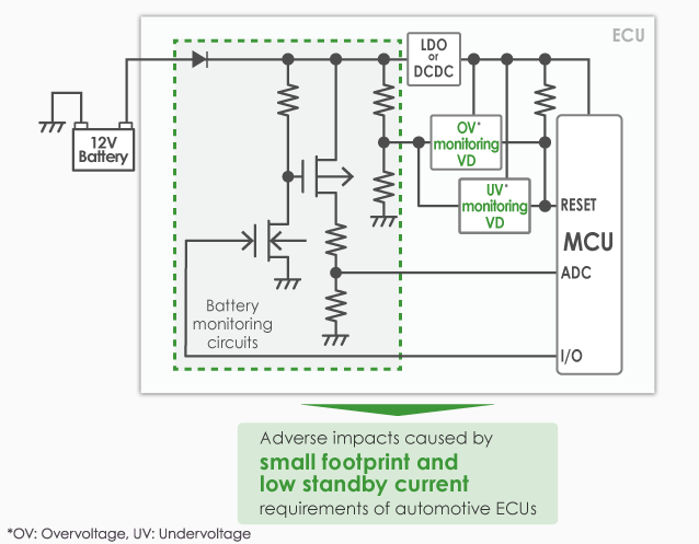
Isolator ADC Figure 1. Typical monitoring and Over-current detection circuit in a BMS Typical monitoring circuits consist of a shunt resistor in series with the system load. The voltage drop across this shunt resistor in indicative of the load current. BMS - Battery management system. A battery management system monitors and controls the charging and discharging state of the battery. my post may not be helpfully for you to design an entire BMS but you can use this to customize/upgrade your BMS systems which can monitor the cell voltage, Battery charging and discharging state.
The ESP32 uses analog input pins (ADC) to read the battery voltage through a voltage divider circuit and the temperature via an NTC thermistor. The measured data is processed using custom formulas and displayed on an IoT cloud dashboard for real-time monitoring.
Understanding the Circuit Diagram of a Battery Management System
Learn how to monitor battery voltage for your battery-powered projects. With code examples, and tips for accurate monitoring.
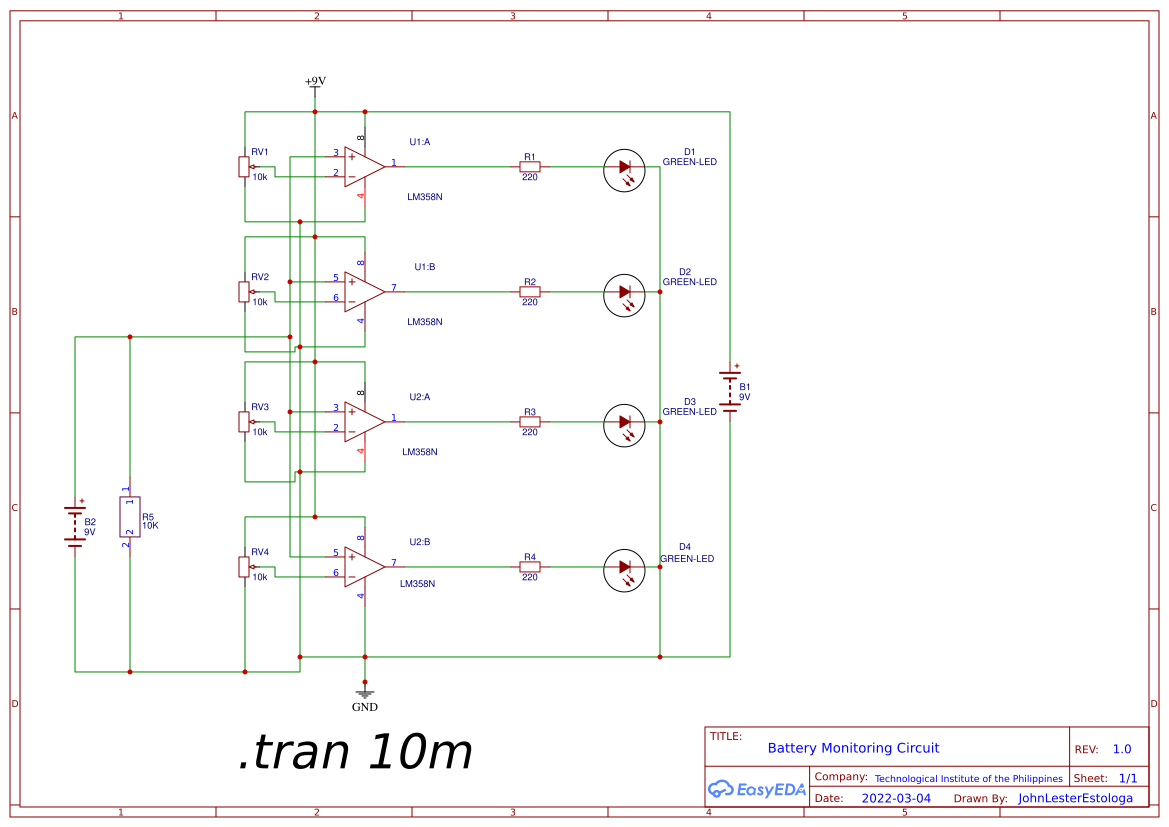
The complete circuit diagram for monitoring Multicell voltage in Lithium Battery Pack is given below. The circuit was designed using EasyEDA and we will use the same to fabricate our PCB also. We are going to design a simple system to monitor battery voltage and battery percentage along with charging and discharging status in Arduino IoT Cloud. A microcontroller is required to send those values to the IoT Platform.
